
Tecnología basada en análisis espectral (VSPECT) y alta resolución


Resumen
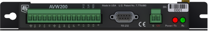
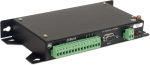
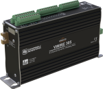
El interface AVW200 permite a nuestros dataloggers medir la señal de cuerda vibrante de extensómetros, transductores de presión, piezómetros, inclinómetros, medidores de grietas y células de carga. Este tipo de sensor y tecnología es utilizada en una amplia variedad de aplicaciones como en estructuras, hidrología y geotécnia, por su estabilidad, precisión y durabilidad.
Learn about our patented VSPECT® spectral-analysis technology at our VSPECT® Essentials web resource.
The dynamic vibrating wire measurement technique is protected under U.S. Patent No. 8,671,758, and the vibrating wire spectral-analysis technology (VSPECT®) is protected under U.S. Patent No. 7,779,690.
Leer másVentajas y características
- Proporciona mejores medidas al reducir significativamente los efectos de ruido externo
- Conexión de hasta dos sensores de cuerda vibrante; se pueden conectar mas sensores con multiplexores AM16/32B
- Diagnósticos de auto-chequeo proporcionan información continua de las condiciones del sensor
- Alta resolución—menos de 0.001Hz (el estándar es de 0.1Hz)
- Bajo consumo
- Integra las medidas de temperatura y frecuencia de sensores de cuerda vibrante
Imágenes


Ficheros CAD:
Descripción detallada
El AVW200 utiliza un innovador método de interpolación espectral para medir la frecuencia de resonancia del sensor. Con el método de interpolación espectral, el módulo excita al sensor de cuerda vibrante, midiendo la respuesta, y le realiza una transformada de Fourier; y devuelve el resultado con una resolución mejor de 0.001Hz—todo en dos segundos. Debido a que el análisis espectral puede distinguir señales de ruido en el espectro, este método ofrece buena inmunidad al ruido.
El módulo AVW200 también proporciona auto-diagnósticos como potencia de la señal del elemento vibrante, relación señal-ruido, ratio de deterioro del elemento vibrante, y respuesta de señal incorrecta. Estos diagnósticos se pueden ejecutar en segundo plano para dar así información contínua de las condiciones de cada sensor.
Preguntas frecuentes
Número de FAQs relacionadas con AVW200: 9
Expandir todoDesplegar todo
-
The AVW200-series modules are not required, but they do reduce the chance of erroneous readings by filtering electrical noise that is sometimes present.
-
The AVW200 must be wired directly to the data logger via a cable.
The AVW206, AVW2011, and AVW216 have built-in spread-spectrum radios tuned to different frequencies that allow the data logger to communicate with a remote AVW device through an appropriate radio link.
-
Two probable causes are the following:
- The SerialOpen() instruction has not been added to the datalogger code.
- The correct PakBus address setting has not been used in the AVW200 instruction.
-
Use pn 17855, Data Cable, RS-232 Male to Pigtail.
-
Yes, using a null modem cable.
-
It takes 2 s for the AVW200-series modules to acquire a measurement from each sensor. An AVW200-series module servicing two AM16/32B multiplexers, each with 16 vibrating wire sensors, requires approximately 64 s to acquire data.
-
Two multiplexers, each with a maximum of 16 or 32 sensors per multiplexer, can be attached. If temperature measurements are excluded from each sensor, 32 sensors are possible.
-
Dozens of AVW200-series modules can be accessed through one CR1000. The limiting factor is the frequency at which the CR1000 is set to retrieve data from each module. If the CR1000 needs to collect data very frequently from the modules, fewer AVW200-series modules can be accommodated in the time between data collection events.
Compatibilidad
Nota: lo siguiente muestra información de compatibilidad notable. No es una lista de todos los productos compatibles.
Dataloggers
| Producto | Compatible | Nota |
|---|---|---|
| 21X (retired) | ||
| CR10 (retired) | The CR10 supports the SDI-12 mode only. | |
| CR1000 (retired) | ||
| CR1000X (retired) | ||
| CR1000Xe | ||
| CR10X (retired) | The CR10X supports the SDI-12 mode only. | |
| CR200X (retired) | ||
| CR216X (retired) | ||
| CR23X (retired) | The CR23X supports the SDI-12 mode only. | |
| CR300 (retired) | ||
| CR3000 (retired) | ||
| CR310 | ||
| CR350 | ||
| CR500 (retired) | ||
| CR5000 (retired) | The CR5000 supports the SDI-12 mode only. | |
| CR510 (retired) | ||
| CR6 | The CR6 is compatible with the AVW200. However, because the CR6 has built-in vibrating wire measurement capabilities, the AVW200 is unnecessary. | |
| CR800 (retired) | ||
| CR850 (retired) | ||
| CR9000 (retired) | ||
| CR9000X (retired) |
Equipos para montajes
| Producto | Compatible | Nota |
|---|---|---|
| ENC10/12 | If using the RS-232 port, the AVW200 must be mounted flat to fit in an ENC10/12. | |
| ENC12/14 | If using the RS-232 port, the AVW200 must be mounted flat to fit in an ENC12/14. | |
| ENC14/16 | ||
| ENC16/18 |
Información de compatibilidad adicional
Sensores
El módulo AVW200 (analizador espectro cuerda vibrante) permite a nuestros dataloggers medir la señal de cuerda vibrante de extensómetros, transductores de presión, piezómetros, inclinómetros, medidores de grietas y células de carga.
Conexiones al datalogger
Si se utiliza SDI-12, se necesita un cable de tres hilos; Campbell Scientific recomienda el cable CABLE3CBL-L. Si se utiliza RS-232, el módulo se conecta al puerto RS-232 del datalogger mediante el cable null modem 18663, o a un par de puertos de control en los dataloggers CR800, CR850, CR1000, o CR3000 mediante el cable 17855.
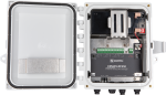
Consideraciones armario
El AVW200 requiere un ambiente sin condensación y con bolsas de desecante; recomendamos usar nuestros armarios. El AVW200 tiene unas aletas agujereadas para su fijación a la placa de montaje de nuestros armarios Campbell Scientific.
Consideraciones alimentación
El AVW200 se alimenta típicamente desde la fuente de alimentación del datalogger.
Especificaciones
| -NOTE- | Electrical specifications are valid over a -25° to +50°C range unless otherwise specified. Non-condensing environment required. |
| Number of Vibrating Wire Sensors Measured | Up to 2 vibrating wire sensors can be connected to the analyzer module. Additional sensors can be measured by using an AM16/32-series multiplexer. |
| Power Requirements | 9.6 to 16 Vdc |
| Analog Input/Outputs | 2 differential (DF) vibrating wire measurements (V+ and V-) and 2 single-ended (SE) ratiometric resistive half-bridge measurements (T+ and T-) for vibrating wire sensor's onboard temperature sensor. |
| Digital Control Ports |
3 digital control ports (C1 – C3)
|
| RS-232 Port | 1 9-pin RS-232 port (for connecting to a data logger COM port) |
| Measurement Resolution | 0.001 Hz RMS (±250 mV differential input range; -55° to +85°C) |
| Measurement Accuracy | ±0.013% of reading (±250 mV differential input range; -55° to +85°C) |
| Input Voltage Range | ±250 mV (differential) for vibrating wire inputs |
| Common Mode Range | ±25 V |
| Baud Rates | Selectable from 1200 to 38.4 kbps. (ASCII protocol is one start bit, one stop bit, eight data bits, and no parity.) |
| Memory |
|
| CE Compliance Standards to which Conformity Is Declared | IEC61326:2002 |
| Dimensions | 21.6 x 11.18 x 3.18 cm (8.5 x 4.4 x 1.25 in.) |
| Weight | 0.43 kg (0.95 lb) |
Typical Current Drain @ 12 Vdc |
|
| Quiescent, Radio Off | ~0.3 mA |
| Radio Duty Cycling 1 s | ~3 mA (includes quiescent current) |
| Radio Always On | ~26 mA (radio transmit current 100 mA) |
| Active RS-232 Communication | ~6 mA (3 s after communication stops, the current will drop to the quiescent current.) |
| Measurement | ~25 mA (averaged over the 2 s) |
Documentos
Folletos producto
Casos de aplicación
Conformidad


Descargas
AVW200 OS v.06 (551 KB) 10-06-2016
Current AVW200 firmware. Use the Device Configuration Utility version 1.13 or greater to send firmware and to configure the AVW200.
AVW200 Program Examples v.1 (8 KB) 31-01-2025
Example programs for the AVW200 and AVW206. The examples demonstrate a direct RS-232 connection to the AVW200, a wireless connection to an AVW206, an SDI-12 connection to the AVW200 and using multiplexers with the AVW200.
Casos de aplicación

In 2022, as Hurricane Fiona unleashed relentless rain on Puerto Rico, the Puerto Rico Landslide......leer más
The Homestake Neutrino Experiment—also referred to as the “Davis Experiment” after physicist Ray Davis, who......leer más

Background In 2022, ECR Medio Ambiente assumed the responsibility of overseeing the structural monitoring installation at......leer más

Located beneath a steep canyon near Douglas, Wyoming sits LaPrele Dam, privately owned by LaPrele......leer más
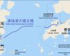
The Hong Kong-Zhuhai-Macao Bridge (HZMB)—comprising viaduct bridges, cable-stayed bridges, a submerged tunnel, and artificial islands—is......leer más

Everglades National Park is the largest tropical wilderness in the United States and was created......leer más

The Delaware Department of Transportation (DelDOT) notified Intelligent Infrastructure Systems (IIS) and Pennoni of the......leer más

Intelligent Infrastructure Systems, a Pennoni company, was contracted to design and install an efficient structural-health......leer más