Nivel de agua / CS475
RETIRED ›
This product is not available for new orders. We recommend ordering: CS475A.
This product is not available for new orders. We recommend ordering: CS475A.
| Services Available |
|---|
Resumen
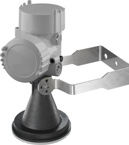
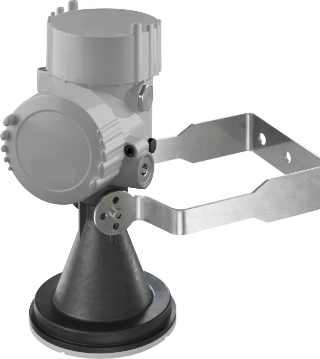
El CS475 es un sensor tipo radar que monitoriza el nivel de agua en ríos, lagos, mar, depósitos, etc... Puede medir distancia hasta 20 metros. La salida de señal del CS475 es digital SDI-12. La mayoría de nuestros dataloggers pueden medir la señal SDI-12.
Leer másVentajas y características
- Conformidad FCC para uso en el exterior (FCC IC number M01PULS616263)
- Ideal en areas que los sensores sumergidos pueden dañarse por la corrosión, contaminación, escombros inundaciones, descargas eléctricas o vandalismo
- Compatible con la mayoría de dataloggers Campbell Scientific
- Bajo mantenimiento - sin partes móviles que reducen significantemente costes de mantenimiento y tiempo
- Low power consumption
- Rugged enough for harsh environments—NEMA rated 4X
- Amplio rango de temperatura de funcionamiento (-40° a +80°C)
Imágenes
Descripción detallada
The CS475 emits short microwave pulses and then measures the elapsed time between the emission and return of the pulses. The elapsed time measurement is used to calculate the distance between the sensor and the target (e.g., water, grain, slurry). The distance value can then be used to determine depth.
Productos similares
Compatibilidad
Nota: lo siguiente muestra información de compatibilidad notable. No es una lista de todos los productos compatibles.
Especificaciones
| Conformidad | FCC approved for outdoor use (FCC IC number M01PULS616263) |
| Rango de medida | 50 mm to 20 m (2 in. to 65 ft) |
| Precisión | ±5 mm (±0.2 in.) over entire measurement range |
| Resolución | 1 mm (0.04 in.) |
| Output Options | SDI-12 |
| Radar Frequency | ~26 GHz |
| Electromagnetic Compatibility | Emission to EN 61326; Electrical Equipment Class B |
| Pulse Energy | 1 mW maximum |
| Beam Angle | 10° |
| Input Voltage | 9.6 to 16 Vdc |
| Surge Protection | 1.5 KVA |
| Rango temperatura funcionamiento | -40° to +80°C |
| Temperature Sensitivity |
|
| Vibration Resistance | Mechanical vibrations with 4 g and 5 to 100 Hz |
| Housing Rating | NEMA 4x |
| Housing Material | Aluminum, coated IP66/68 |
| Horn Material | PVDF encapsulated plastic |
| Typical Sleep Current Drain | 4.7 mA (with 12 V power supply) |
| Typical Measurement Current Drain | 14 mA (with 12 V power supply) |
| Side Cap Diameter | 8.6 cm (3.4 in.) |
| End Cap Diameter | 8.6 cm (3.4 in.) |
| Horn Diameter | 7.5 cm (3 in.) |
| Head Width | 11 cm (4.3 in.) |
| Horn Length | 13.7 cm (5.4 in.) |
| Total Length | 26.6 cm (10.5 in.) |
| Peso |
|
Documentos
Folletos producto
Casos de aplicación
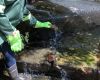
The Jukskei River is one of the largest rivers in Johannesburg, South Africa. The river......leer más
Water and Earth Technologies (WET), a Campbell Scientific integrator, is a water resources and environmental engineering firm.......leer más
Water and Earth Technologies (WET), a Campbell Scientific integrator, is a water resources and environmental engineering firm.......leer más