This product is not available for new orders. We recommend ordering: CS301.
| Services Available |
|---|
Resumen
El CS300 mide la radiación solar global, para aplicaciones relacionadas con la energía solar, agricultura, meteorología e hidrología. Su respuesta espectral es de 300 a 1000 nm, que es la radiación solar que mayoritariamente alcanza la superficie de la Tierra. Este piranómetro se conecta directamente a cualquiera de nuestros dataloggers.
Leer másVentajas y características
- Compatible con todos los datalogger Campbell Scientific (incluso serie CR200(X) )
- Diseñado para funcionamiento en continuo, largo tiempo, desatendido y en condiciones adversas
- Longitud de onda: 360 a 1120 nm
- La forma en cúpula del cabezal previene la acumulación de agua
Imágenes
Descripción detallada
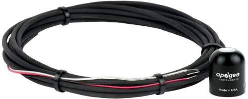
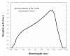
The CS300 uses a silicon photovoltaic detector mounted in a cosine-corrected head to provide solar radiation measurements for solar, agricultural, meteorological, and hydrological applications. Calibrated against a Kipp & Zonen CM21 thermopile pyranometer, the CS300 accurately measures sun plus sky radiation for the spectral range of 360 to 1120 nm. Sensors calibrated to this spectral range should not be used under vegetation or artificial lights.
The standard output is 0.2 mV per W m-2, which provides a signal of 200 mV in full sunlight (1000 W m-2). All of our dataloggers, including the CR200(X) series, can measure this output.
Productos similares
Preguntas frecuentes
Número de FAQs relacionadas con CS300: 6
Expandir todoDesplegar todo
-
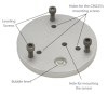
The leveling base provides physical stability and helps ensure the sensor is leveled correctly. It is not recommended to use the sensor without the base. The sensor mounts to the base with an included bolt. However, a user-supplied plate with a hole drilled in it could be used instead to accept the sensor’s mounting bolt.
Note: Whatever mounting method is used, the sensor has to be levelled to operate correctly.
-
Campbell Scientific does not recommend splicing any cable into the existing cable. Splicing a cable could introduce water and electrical noise into the connection. The sensor can be ordered with longer cable lengths, and 50 m is right on the edge of the recommended length. With a cable this long, Campbell Scientific recommends measuring the sensor differentially using the following wiring conventions:
Wire Color
Datalogger Channel
RED
Diff Channel H
BLACK
Diff Channel L
CLEAR (SHIELD)
AG or Ground Symbol
JUMPER WIRE
Diff Channel L to AG or Ground Symbol
In the datalogger program, a differential voltage instruction needs to be used instead of a single-ended voltage instruction.
-
No. It’s not the range that makes a sensor a quantum sensor. It is the type of light filter used with the photocell that only allows specific wavelengths of light in the PAR frequency range to strike the photocell.
-
Compare the sensor against a recently calibrated CS300-L on a clear, sunny day with the sun overhead. Ensure that the sensor being used as a reference is also level.
-
To incorporate a sensor that is compatible with wireless sensor interfaces into a wireless network, a CWS900-series wireless sensor interface is needed, as well as an A205 CWS-to-PC interface to configure it.
Compatibilidad
Nota: lo siguiente muestra información de compatibilidad notable. No es una lista de todos los productos compatibles.
Dataloggers
| Producto | Compatible | Nota |
|---|---|---|
| 21X (retired) | ||
| CR10 (retired) | ||
| CR1000 (retired) | ||
| CR1000X (retired) | ||
| CR10X (retired) | ||
| CR200X (retired) | ||
| CR216X (retired) | ||
| CR23X (retired) | ||
| CR300 (retired) | ||
| CR3000 (retired) | ||
| CR310 | ||
| CR500 (retired) | ||
| CR5000 (retired) | ||
| CR510 (retired) | ||
| CR6 | ||
| CR800 (retired) | ||
| CR850 (retired) | ||
| CR9000 (retired) | ||
| CR9000X (retired) |
Información de compatibilidad adicional
Sensor Mounts
Accurate measurements require the sensor to be leveled using a 18356 leveling fixture. This leveling fixture incorporates a bubble level and three adjusting screws. The 18356 mounts to a crossarm or a tripod or tower mast using the CM225 mounting stand. The CS300 should be mounted away from all obstructions and reflective surfaces that might adversely effect the measurement.
Datalogger Considerations
One differential analog input channel per probe is required.
Especificaciones
| Spectral Range | 360 to 1120 nm (wavelengths where response is 10% of maximum) |
| Measurement Range | 0 to 2000 W/m2 (full sunlight ≈1000 W/m2) |
| Absolute Accuracy | ±5% for daily total radiation |
| Sensitivity | 5 mV/Wm-2 |
| Calibration Factor | 5 W/m2/mV |
| Cosine Correction Error | ±5% at 75° zenith angle; ±2% at 45° zenith angle |
| Temperature Response | 0.04 ± 0.04% per °C |
| Response Time | < 1 ms |
| Long-Term Stability | < 2% per year |
| Operating Temperature Range | -40° to +70°C |
| Relative Humidity Range | 0 to 100% |
| Output Sensitivity | 0.2 mV/W/m2 |
| Diameter | 2.4 cm (0.9 in.) |
| Height | 2.5 cm (1.0 in.) |
| Weight | 65 g (2.3 oz) with 2-m (6.6-ft) lead wire |
Documentos
Folletos producto
Manuales
Casos de aplicación
Dr. Joan Girona of the Institute of Agroalimentary Research and Technology in Catalonia, Spain, studies......leer más