Resumen
El VDIV2:1 utiliza resistencias de precisión para adaptar un nivel alto de voltaje de un sensor al rango de entrada del datalogger, permitiendo al datalogger medir ese sensor. El VDIV10:2 divide la señal de voltaje del sensor a la mitad.
Leer más
Ventajas y características
- Se conecta directamente en los terminales de entrada del datalogger
- Fácil de instalar o quitar
- Bajo consumo
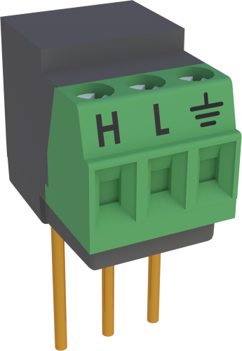
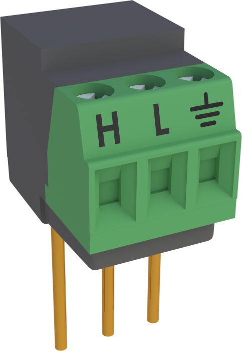
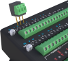
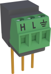
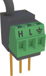
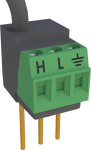
Imágenes
Descripción detallada
El VDIV2:1 contiene dos resistencias de 10kohm con una tolerancia del ±0.02%.Puede ser necesario incrementar el ‘settling time’ de entrada para adecuar la relativa alta resistencia del divisor de tensión.
Productos similares
Preguntas frecuentes
Número de FAQs relacionadas con VDIV2:1: 2
-
These two voltage dividers can handle different maximum input voltages.
- The VDIV2:1 has a maximum input voltage of 10 V.
- The VDIV10:1 has a maximum input voltage of 50 V.
-
The CR1000 has analog inputs that measure voltage in a ±5 Vdc range. To measure a 12 Vdc voltage, a voltage divider is needed. In its simplest form, a voltage divider comprises two resistors. Precision differential voltage dividers, such as the VDIV10:1, are available for this purpose.
Compatibilidad
Nota: lo siguiente muestra información de compatibilidad notable. No es una lista de todos los productos compatibles.
Dataloggers
| Producto | Compatible | Nota |
|---|---|---|
| 21X (retired) | ||
| CR10 (retired) | ||
| CR1000 (retired) | ||
| CR10X (retired) | ||
| CR200X (retired) | ||
| CR216X (retired) | ||
| CR23X (retired) | ||
| CR300 (retired) | ||
| CR3000 (retired) | ||
| CR310 | ||
| CR350 | ||
| CR500 (retired) | ||
| CR5000 (retired) | ||
| CR510 (retired) | ||
| CR6 | ||
| CR800 (retired) | ||
| CR850 (retired) | ||
| CR9000 (retired) | Compatible CR9000 modules are the CR9050 and the CR9052; the CR9051 is partially compatible. | |
| CR9000X (retired) | Compatible CR9000X modules are the CR9050 and the CR9052; the CR9051 is partially compatible. |
Información de compatibilidad adicional
Consideraciones datalogger
El VDI2:1 utiliza dos entradas analógicas adyacentes (un canal diferencial); el canal analógico de tierra adyacente es para la patilla de tierra del VDIV2:1 No todos los regleteros de los dataloggers tienen esta secuencia en todos los canales, por tanto compruebe el panel de conexiones de su datalogger para confirmar la asignación de canales, especialmente si planea utilizar múltiples módulos acondicionadores.
Programación
El VDIV2:1 se mide con la instrucción VoltSE o VoltDiff en CRBasic y con la Instruction 1 (SE Volts) o 2 (DiffVolts) en Edlog. Cada VDIV2:1 puede ser cableado para hacer una medida diferencial o dos medidas single-ended.
Especificaciones
| Used With | Sensors with a high voltage ouptut |
| Division Ratio | 2:1 |
| Resistance | 10 kΩ and 10 kΩ |
| Tolerance | Ratio: ±0.02% (@ 25°C) |
| Power Rating | 0.1 W (@ 70°C) per element |
| Maximum Temperature Coefficient | Ratio: 2 ppm/°C (0° to 70°C) |
| Dimensions | 1.5 x 1.5 x 2.7 cm (0.6 x 0.6 x 1.0 in.) for body with prongs |
| Weight | 6 g (0.2 oz) |
Documentos
Descargas
VDIV Program Example (1 KB) 29-07-2022
In this example program, a VDIV10:1 and the VoltDiff() instruction are used to measure an input voltage with a maximum voltage of 14 VDC, as described in the VDIV10.1/VDIV2.1 manual.