CS120A Sensor de visibilidad
Sensor visibilidad de alto rendimiento a precio económico
meteorología aplicaciones agua aplicaciones energía aplicaciones flujo gas y turbulencia aplicaciones infraestructuras aplicaciones suelo aplicaciones

Resumen

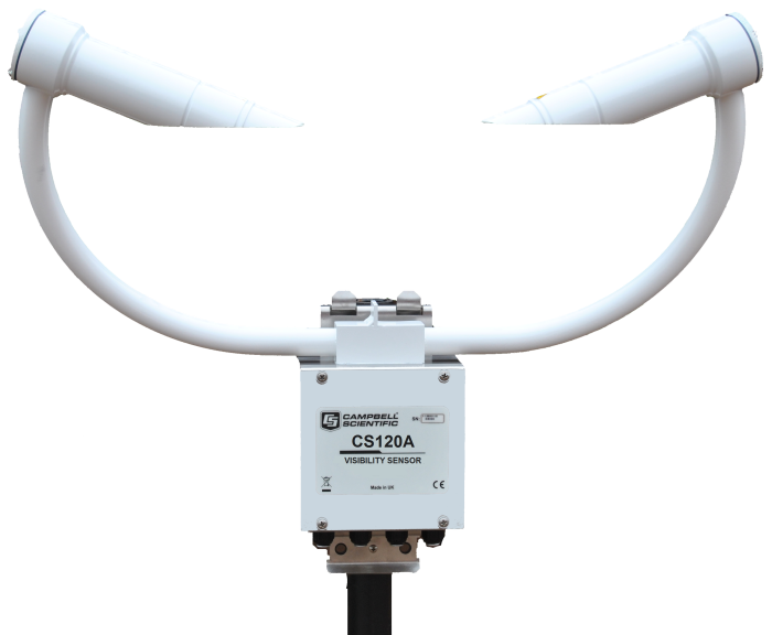
El CS120A es un sensor de visibilidad por infrarrojos de dispersión frontal para uso autónomo o en una estación meteorológica automática, para aplicaciones en carreteras, marinas y aeropuertos. El CS120A utiliza la conocida técnica de dispersión frontal para determinar la visibilidad, utilizando un ángulo de dispersión de 42° que proporciona estimaciones precisas del Meteorological Observable Range (M.O.R.) para niebla y nieve.

Para aplicaciones aeronáuticas el CS120A cumple normativas CAA y ICAO; y también las CAP437, CAP670 y CAP746.

Certificado por el Deutscher Wetterdienst para controlar la luminosidad de las balizas luminosas en los aerogeneradores de parques eólicos, según norma 506/04, General Administrative Rules for the Identification of Aircraft Obstructions.

Leer más

Ventajas y características

  • Sensor de alto rendimiento a precio competitivo
  • Disponible extensión garantía de 3 años
  • El diseño del sensor minimiza la interrupción del flujo de aire en el volumen de medición
  • Incluye calentadores en cabezales (hood) y lentes (dew) para funcionamiento en todo tipo de condiciones meteorológicas
  • Calibración en campo mediante kit de calibración opcional
  • Bajo consumo - adecuado para aplicaciones remotas
  • Sensor design minimizes airflow disruption at measurement volume
  • Fabricado en UK
  • Certificado para uso aeronáutico por el German Meteorological Service DWD

Imágenes

Descripción detallada

Comparado con sensores de otros fabricantes, el diseño del CS120A permite medir la visibilidad en un espacio relativamente limpio, porqué la posición de los cabezales y cuerpo del sensor minimizan la perturbación del flujo de aire en el volumen de medición.

El CS120A utiliza muestreo a alta velocidad continuo, que mejora la precisión de las medidas tomadas en condiciones de lluvia y granizo, y proporciona lecturas fiables durante situaciones más estables como niebla y neblina. El muestreo a alta velocidad también permite que el sensor responda mejor ante cambios repentinos de las condiciones meteorológicas.

El diseño característico del CS120A permite mantener limpias las ópticas. Las ópticas mirando hacia abajo minimizan la acumulación de suciedad y nieve. Los calentadores de bajo consumo (dew heaters) evitan la formación de escarcha, mientras que los calentadores de alto consumo (hood heaters) evitan la formación de hielo.

El sensor tiene un consumo muy eficiente, de tan sólo 3 W durante un funcionamiento normal con los calentadores contra escarcha (dew heaters) activos; se puede reducir el consumo posteriormente bajando la velocidad de muestreo y realizando el control manual de los calentadores.

Hay disponibles dos salidas de alarma mediante relés, que pueden activar sistemas de aviso externos como sirenas y semáforos. También se pueden utilizar, dependiendo de los niveles de visibilidad, para controlar la intensidad lumínica de las balizas luminosas en los aerogeneradores.

Especificaciones

Signal Type/Output RS-232, RS-485
Measurement Description Meteorological Observable Range (MOR)
Maximum Reported Visibility 100 km (62.1 mi)
Minimum Reported Visibility 5 m (16.4 ft)
Accuracy
  • ±8% at < 600 m (< 1968.5 ft)
  • ±10% at 600 to 10,000 m (1968.5 to 32,808.4 ft)
  • ±15% at 10,000 to 15,000 m (32,808.4 to 49,212.6 ft)
  • ±20% at 15,000 to 75,000 m (49,212.6 to 246,063 ft)
Resolution 1 m (3.3 ft)
Mounting Stainless-steel V-bolt bracket that attaches to a pole with a 32 to 52.5 mm (1.25 to 2 in.) outer diameter
Electronics Supply Voltage 7 to 30 Vdc
Total Unit Power < 3 W while sampling continuously (including dew heaters)
Standards Frangible masts are available to customer requirements to meet ICAO recommendations (typically placing the sample volume at 2.5 m [8.2 ft]).
Sensor Dimensions 540 x 640 x 246 mm (21.26 x 25.2 x 9.7 in.) including mount
Sensor Weight ~3 kg (6.6 lb) depending on mounting system

Optical/Pulse

LED Center Wavelength 850 nm
LED Spectral Bandwidth ±35 nm
Light Pulse Rate 1 kHz

Environmental

Operating Temperature Range -25° to +60°C (standard)
Extended Operating Temperature Range -40° to +70°C (This extended version is available as a special. Contact Campbell Scientific for more information.)
Operating Humidity Range 0 to 100%
Sensor Sealing Rated to IP66
Wind Speed Up to 60 m s-1
Sensor Heater Threshold
  • < 35°C (dew heater on)
  • > 40°C (dew heater off)
  • < 15°C (hood heater on)
  • > 25°C (hood heater off)

DSP & Dew Heaters

Power 2 x 0.6 W (total of 1.4 W) for dew heater
Typical Current Consumption @ 12 Vdc
  • 200 mA (continuous sampling, dew heaters active)
  • 110 mA (continuous sampling, dew heaters disabled)
  • 21 mA (no sampling, dew heaters disabled)
  • 200 mA (dew heaters active, RS-232 communications)

Hood Heater

Supply Voltage 24 V dc or ac
Power 2 x 30 W (total of 60 W)

Interface

Serial Interface RS-232 or RS-485, 8 bit data bytes, 1 stop bit
Serial Data Rates 1200 to 115,200 bps (38,400 bps default rate)

Compatibilidad

Nota: lo siguiente muestra información de compatibilidad notable. No es una lista de todos los productos compatibles.

Dataloggers

Producto Compatible Nota
CR1000 (retired)
CR1000X
CR300
CR3000 (retired)
CR310
CR350
CR6
CR800 (retired)
CR850 (retired)

Descargas

CR1000X CS120A example programs v.1 (2 KB) 18-03-2020

CR1000X programs that use the MSSET and MSGET commands.


CS125 and CS120A OS v.17 (555 KB) 08-06-2023

Campbell Scientific has introduced a new operating system, OS 17, for the CS120A visibility sensor and CS125 present weather sensor. It is backwards compatible and is easily installed on all CS120A and CS125 sensors (but not older CS120 sensors). OS 17 is available free of charge and can be downloaded here or supplied by email on request.

Upgrade to OS 17 is recommended.

Historial revisiones

Campbell Viewpoint v.2.1.0.2 (86 MB) 09-10-2019

Campbell Viewpoint is viewing software designed to accompany the Campbell Scientific optical sensor range, including the CS135 ceilometer, SkyVue PRO, SkyVue 8, SkyVue 8M, CS120A visibility and CS125 present weather sensors. It is free to download (or via email on request) and use for 100 hours, after which you will need to purchase a key to continue using it.

Version 2.1.0.2

Viewpoint version 2.1.0.2 has introduced our new ceilometer sensors to the list of instruments that can be monitored.  This includes the SkyVue PRO, SkyVue 8 and SkyVue 8M.  

Previous sensors are still available.

Version 2.1.0.2 also includes some minor bug fixes and improvements to the help menu.

Preguntas frecuentes

Número de FAQs relacionadas con CS120A: 3

Expandir todoDesplegar todo

  1. Most Campbell Scientific sensors are available as an –L, which indicates a user-specified cable length. If a sensor is listed as an –LX model (where “X” is some other character), that sensor’s cable has a user-specified length, but it terminates with a specific connector for a unique system:

    • An –LC model has a user-specified cable length for connection to an ET107, CS110, or retired Metdata1.
    • An –LQ model has a user-specified cable length for connection to a RAWS-P weather station.

    If a sensor does not have an –L or other –LX designation after the main model number, the sensor has a set cable length. The cable length is listed at the end of the Description field in the product’s Ordering information. For example, the 034B-ET model has a description of “Met One Wind Set for ET Station, 67 inch Cable.” Products with a set cable length terminate, as a default, with pigtails.

    If a cable terminates with a special connector for a unique system, the end of the model number designates which system. For example, the 034B-ET model designates the sensor as a 034B for an ET107 system.

    • –ET models terminate with the connector for an ET107 weather station.
    • –ETM models terminate with the connector for an ET107 weather station, but they also include a special system mounting, which is often convenient when purchasing a replacement part.
    • –QD models terminate with the connector for a RAWS-F Quick Deployment Station.
    • –PW models terminate with the connector for a PWENC or pre-wired system.
  2. Not every sensor has different cable termination options. The options available for a particular sensor can be checked by looking in two places in the Ordering information area of the sensor product page:

    • Model number
    • Cable Termination Options list

    If a sensor is offered in an –ET, –ETM, –LC, –LQ, or –QD version, that option’s availability is reflected in the sensor model number. For example, the 034B is offered as the 034B-ET, 034B-ETM, 034B-LC, 034B-LQ, and 034B-QD.

    All of the other cable termination options, if available, are listed on the Ordering information area of the sensor product page under “Cable Termination Options.” For example, the 034B-L Wind Set is offered with the –CWS, –PT, and –PW options, as shown in the Ordering information area of the 034B-L product page.

    Note: As newer products are added to our inventory, typically, we will list multiple cable termination options under a single sensor model rather than creating multiple model numbers. For example, the HC2S3-L has a –C cable termination option for connecting it to a CS110 instead of offering an HC2S3-LC model. 

  3. Many Campbell Scientific sensors are available with different cable termination options. These options include the following:

    • The –PT (–PT w/Tinned Wires) option is the default option and does not display on the product line as the other options do. The cable terminates in pigtails that connect directly to a datalogger.
    • In the –C (–C w/ET/CS110 Connector) option, the cable terminates in a connector that attaches to a CS110 Electric Field Meter or an ET-series weather station.
    • In the –CWS (–CWS w/CWS900 Connector) option, the cable terminates in a connector that attaches to a CWS900-series interface. Connection to a CWS900-series interface allows the sensor to be used in a wireless sensor network.
    • In the –PW (–PW w/Pre-Wire Connector) option, the cable terminates in a connector that attaches to a prewired enclosure.
    • In the –RQ (–RQ w/RAWS Connector) option, the cable terminates in a connector that attaches to a RAWS-P Permanent Remote Automated Weather Station.

    Note: The availability of cable termination options varies by sensor. For example, sensors may have none, two, or several options to choose from. If a desired option is not listed for a specific sensor, contact Campbell Scientific for assistance.

Casos de aplicación

Instrumented Runway Visual Range (IRVR) System for Civil Aviation
Exeter Airport is undergoing a huge refurbishment to expand their capabilities and streamline their operations......leer más
Utah: CS125 in Road Weather Network
The Utah Department Of Transportation (UDOT) operates a network of roadside weather stations across the......leer más
Cloud Base & Visibility Sensors for Military Aviation
AUDIMOBIL recently installed an Automatic Weather Station in a Portuguese Military Air Base, to support......leer más