Puede usarse en variedad de aplicaciones


Resumen
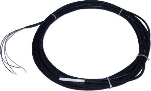
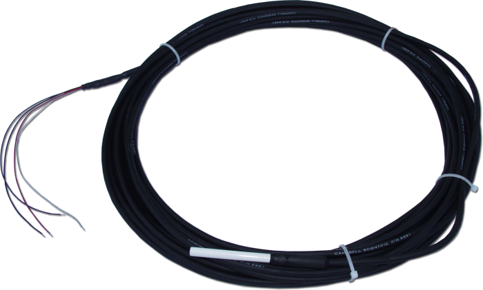
El sensor 108 es robusto y preciso, mide la temperatura del aire, suelo o agua de -5° a +95°C. Se conecta fácilmente a la mayoría de nuestros dataloggers Campbell Scientific y puede usarse en variedad de aplicaciones.
Leer másVentajas y características
- Producto versátil—mide temperatura del aire, suelo o agua
- Fácil de instalar o quitar
- Durable
- Compatible con multiplexores AM16/32, permitiendo medir múltiples sensores
Imágenes
Descripción detallada
El sensor 108 consiste en un termistor encapsulado dentro de una vaina de acero inoxidable rellenada con "epoxy". El encapsulado protege el termistor tanto si se entierra en el suelo como si se sumerge en el agua.
Preguntas frecuentes
Número de FAQs relacionadas con 108: 4
Expandir todoDesplegar todo
-
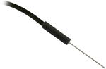
The thermistor is located approximately 3 mm (0.125 in.) back from the probe tip.
-
When these sensors are purchased, the following calibration services are offered: TEMPCAL and TEMPCAL2.
- TEMPCAL provides a single-point calibration and a calibration certificate. The single-point calibration determines the offset at 25°C with an uncertainty of ±0.05°C.
- TEMPCAL2 provides a two-point calibration and a calibration certificate. The two-point calibration determines offsets at 30°C and 65°C with an uncertainty of ±0.05°C.
For both of these services, calibration can be made at different values if it is requested by the purchaser at the time of purchase. In addition, both of these calibration services can be requested after sensor purchase using a return material authorization (RMA) number. To request an RMA number, refer to the Repair and Calibration page.
-
The sensor/probe consists of a non-linear thermistor configured with a precision resistor in a half-bridge circuit, as shown in the product’s manual:
- Model 107 Temperature Probe Instruction Manual
- Model 108 Temperature Probe Instruction Manual
- 108-LC Temperature Probe for MetData1 Instruction Manual
- Model 109 Temperature Probe Instruction Manual
To measure the sensor/probe, the measurement device has to provide a precision excitation voltage (Campbell Scientific dataloggers use 2000 mV), measure the voltage across the precision resistor, determine the thermistor resistance (Ohm's law), and convert the resistance to temperature using the Steinhart-Hart equation.
The Steinhart-Hart equation is 1/T = A + Bln(R) + C(ln(R))3 where:
- T is the temperature in Kelvin
- R is the resistance at T in ohms
- A, B, and C are the Steinhart-Hart coefficients, which vary depending on the temperature range of interest, as well as the type and model of the thermistor
For the 107-L, 107-LC, 108-L, and 108-LC, the following are the coefficients for the Steinhart-Hart equation:
- A = 8.271111E-4
- B = 2.088020E-4
- C = 8.059200E-8
For the 109-L, the following are the coefficients for the Steinhart-Hart equation:
- A = 1.129241E-3
- B = 2.341077E-4
- C = 8.775468E-8
-
Note the difference between calibration and a field check. Calibration cannot be done in the field, as it requires an experienced technician and specialized equipment.
Field checks of measurements can be done to determine if the data make sense with the real-world conditions. Follow these steps to field check a sensor:
- Find a second sensor of the same type as the installed sensor whose data is in question. The second sensor will be used as a benchmark sensor and should be known to be accurate or recently calibrated.
- At the site, take readings using both sensors under the same conditions. The best practice is to measure both sensors side-by-side at the same time. Note that the sensors will never have the exact same measurement.
- Depending on the sensor model, if the difference in the readings of the installed and benchmark sensors is greater than the sum of the accuracies for both sensors, either return the installed sensor to Campbell Scientific for calibration or replace the appropriate chip.
- The 107, 108, 109, 110PV-L, and BlackGlobe-L temperature sensors can be calibrated.
- The HC2S3-L and HMP155A-L temperature and relative humidity sensors can be calibrated.
- The CS215-L has a replaceable chip for temperature and relative humidity. For more information, refer to the “Maintenance and Calibration” section of the CS215 instruction manual.
- The HMP60-L has a replaceable chip for relative humidity only. For more information, refer to the “Maintenance” section of the HMP60 instruction manual.
Compatibilidad
Nota: lo siguiente muestra información de compatibilidad notable. No es una lista de todos los productos compatibles.
Dataloggers
| Producto | Compatible | Nota |
|---|---|---|
| CR1000 (retired) | ||
| CR300 (retired) | ||
| CR3000 (retired) | ||
| CR310 | ||
| CR350 | ||
| CR6 | ||
| CR800 (retired) | ||
| CR850 (retired) |
Información de compatibilidad adicional
Data Logger Considerations
One single-ended channel per probe is required; an excitation channel can be shared by several probes.
Installation Considerations
Air Temperature
When exposed to sunlight, the 108 should be housed in a 41303-5A, 41303-5B, or RAD06 6-plate radiation shield. The louvered construction of these radiation shields allows air to pass freely through the shield, thereby keeping the sensor at or near ambient temperature. The shields’ white color reflects solar radiation.
The RAD06 uses a double-louvered design that offers improved sensor protection from driving rain, snow, insect intrusion and has lower self-heating in bright sunlight combined with higher temperatures (> 24°C [~75°F]) and low wind speeds (< 2 m/s [~4.5 mph]), giving a better measurement.
The 41303-5A and RAD06 attach to a crossarm, mast, or user-supplied pipe with a 2.5 to 5.3 cm (1.0 in to 2.1 in.) outer diameter. The 41303-5B attaches to a CM500-series pole or a user-supplied pole with a 5.1 cm (2.4 in.) outer diameter.
Soil Temperature
The 108 is suitable for shallow burial only. Placement of the sensor’s cable inside a rugged conduit may be advisable for long cable runs—especially in locations subject to digging, mowing, traffic, use of power tools, or lightning strikes.
Water Temperature
The sensor can be submerged to 15 m (50 ft) or 21 psi. Please note that the 108 is not weighted. Therefore, the installer should either add a weighting system or secure the sensor to a fixed, submerged object, such as a piling.
Multiplexers
To measure large numbers of probes, the AM16/32B multiplexer is recommended.
Especificaciones
| Sensor Description | BetaTherm 100K6A1IA Thermistor |
| Tolerance | ±0.2°C (over 0° to 70°C range) |
| Temperature Measurement Range | -5° to +95°C |
| Steinhart-Hart Equation Error | ≤ ±0.01°C over measurement range (CRBasic data loggers only) |
| Polynomial Linearization Error | Typically < ±0.5°C over -5° to 90°C range (Edlog data loggers only) |
| Time Constant in Air | 30 to 60 s (in a wind speed of 5 m s-1) |
| Maximum Submergence | 15 m (50 ft) |
| Maximum Cable Length | 305 m (1000 ft) |
| Probe Diameter | 0.76 cm (0.3 in.) |
| Probe Length | 10.4 cm (4.1 in.) |
| Weight | 136 g (5 oz) with 3.05 m (10 ft) cable |
Documentos
Folletos producto
Manuales
Documentos técnicos
Conformidad
Casos de aplicación
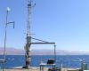
The meteorological stations at the Interuniversity Institute for Marine Sciences at Eilat (IUI) in Israel......leer más