
Resumen
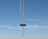
The UT30 is a durable instrument tower that can be used for a variety of applications. The UT30 tower provides a sturdy mount for many meteorological monitoring applications—especially air quality stations and regional Mesonets, where the 10 m (32.81 ft) measurement height for wind sensors is standard. It also holds antennas, solar panels, environmental enclosures, radiation shields, and crossarms. It is a versatile instrument mount: many of the same sensor mounts that are used with either our tripods or other towers can be used with the UT30.
Leer másVentajas y características
- Sturdy, long-term instrument mount
- Corrosion-resistant
Imágenes


Descripción detallada
The UT30 tower includes three 3 m (10 ft) sections, one extendable mast, and two cable tie kits. The extendable mast has a 1.5 m (5 ft) length and a 3.175 cm (1.25 in) outer diameter [swagged to 2.5 cm (1 in) OD].
Top 3 m Section
The top section is constructed from 2.5 cm (1 in) OD aluminum tubing. Its width is 25.7 cm (10.1 in) on a side (center of tubing to center of tubing).
Center 3 m Section
The center section is constructed from 2.5 cm (1 in) OD aluminum tubing. Its width is 33.3 cm (13.1 in) on a side (center of tubing to center of tubing).
Bottom 3 m Section
The bottom section is constructed from 3.175 cm (1.25 in) OD aluminum tubing. Its width is 43.2 cm (17 in) on a side (center of tubing to center of tubing).
Mounting Base, Grounding Kit, and Guying Kit
This tower requires a mounting base and grounding kit. Campbell Scientific also recommends guying the UT30 with our UTGUY Guy Kit. See Ordering Info on the web page for more information.


Preguntas frecuentes
Número de FAQs relacionadas con 6139: 5
Expandir todoDesplegar todo
-
Tower hardware, as well as individual tower sections, can be special ordered if necessary. Contact Campbell Scientific for assistance. If you would prefer to purchase the hardware at a local store, the items are listed below.
- Nuts and bolts for the tower:
- 3/8 in. hex cap
- 2 in. long, zinc plated
- Nuts and bolts for the concrete mounting base:
- 3/8 in. hex cap
- 2 ½ in. long, zinc plated
- Nuts and bolts for the tower:
-
The B18 Concrete Mounting Base must be attached to the bottom tower section before the concrete foundation is poured.
-
The top section of the tower is made of 1" OD aluminum tubing; in cross-section, the topmost tower section is 10.1 inches on a side (center of tubing to center of tubing).
The middle section of the tower is made of 1" OD aluminum tubing; in cross-section, the middle tower section is 13.1 inches on a side (center of tubing to center of tubing).
The bottom section of the tower is made of 1.25" OD aluminum tubing; in cross-section, the middle tower section is 17 inches on a side (center of tubing to center of tubing).
-
Individual tower sections, as well as tower hardware, can be special ordered if necessary. Contact Campbell Scientific for assistance.
-
In applications involving a tower and either strong winds or the need to attach a lot of gear to a crossarm, Campbell Scientific recommends using a longer crossarm with a second CM210 Crossarm-to-Pole Bracket. (One CM210 ships with each CM202, C204, or CM206 crossarm.) Secure the crossarm to two points on the tower to add stability and rigidity to the crossarm. The crossarm can be shifted in a foot (the distance between the vertical supports on the tower), or the crossarm can be centered on the tower.
Compatibilidad
Nota: lo siguiente muestra información de compatibilidad notable. No es una lista de todos los productos compatibles.
Información de compatibilidad adicional
Enclosure Brackets
The “-TM” mount option for our environmental enclosures is used to attach our enclosures to a UT30 tower. An enclosure ordered with the “-TM” option will be shipped with a three-piece bracket mounted to the top of the enclosure and an identical three-piece bracket mounted to the bottom of the enclosure. This mounting bracket option uses the same three-piece brackets as the "-MM" option, except the pieces are rearranged so that the flanges are on the side of the bracket instead of in the middle. The distance between the centers of each flange needs to be 17”.
Note:
Enclosures with the "-TM" option are shipped configured for the UT10 tower. UT30 customers will need to: (1) remove the bolts attaching the bracket to the enclosure, (2) slide out the flange sections so that the distance between the center of each flange is 17", and (3) reattach the bracket to the enclosure using the original bolts.
Especificaciones
| Material | Hardened drawn 6063-T832 aluminum |
| Guyed Tower Area Requirements | ~5 m (17 ft) radius |
| Required Concrete Pad Dimensions |
91 x 91 x 122 cm (36 x 36 x 48 in.) for B18 Concrete Mounting Base Concrete pad requirements assume heavy soil; light, shifting, or sandy soils require a larger concrete pad. |
| Extendable Mast |
|
| Pipe Outer Diameter |
|
| Crossarm Measurement Height | 10 m (33 ft) |
| Height | 10.1 m (33 ft) |
| Shipping Dimensions | 310 x 46 x 46 cm (122 x 18 x 18 in.) |
| Shipping Weight | 29 kg (65 lb) |
Maximum Wind Load Recommendation |
|
| B18 Base (unguyed) | 177 km/h (110 mph) |
| RFM18 Base (with UTGUY) | 177 km/h (110 mph) |
| UTBASE (unguyed) | 177 km/h (110 mph) |
| -NOTE- |
Wind load endurance is affected by quality of anchoring and installation; guy wire tension;
soil type; guy angle; and number, type, and location of instruments fastened to the tower. Wind load recommendation assumes proper installation, proper anchoring, adequate soil, and total instrument projected area of less than 0.19 m2 (2 ft2) at the height of the tower. For the RFM18 base, the wind load recommendation also assumes that the UTGUY’s turnbuckles are preloaded just enough to equalize tension and that the tower is guyed at a 60 degree angle relative to the ground (maximum). |
Documentos
Folletos producto
Documentos técnicos
Videos & Tutoriales
 UTBASE installation with a template frame and 2) UTBASE installation without a template frame. The video is divided into sections. Watch the full video when deciding on the installation method. Once the method is known, use the links in this description to jump directly to the chosen installation section.
00:45 Tools and Site Preparation
01:30 UTBASE Installation With a Template Frame
04:26 UTBASE Installation Without a Template Frame
06:38 Clevis Installation")

Casos de aplicación
The West Texas Mesonet (WTM) project was initiated by Texas Tech University in 1999 to......leer más