Gama de productos
| Reporting Range | Cloud Layers Reported | Temperature Range | Power Source | Military Specification | |
|---|---|---|---|---|---|
SkyVue PRO
|
Instrument Performance: 0 to 10 km (0 to 33,000 ft) | Instrument Performance: Up to four layers |
|
Electrical Specification: 115, 230 Vac ±10%, 50 to 60 Hz, 470 W maximum | — |
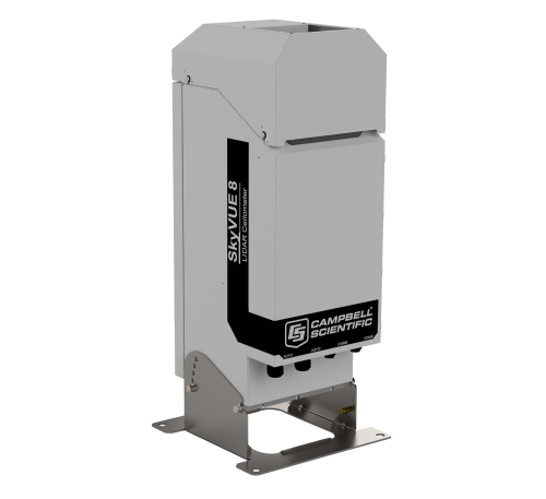
SkyVue 8
|
Instrument Performance: 0 to 8 km (0 to 26,250 ft) | Instrument Performance: Up to four layers |
|
|
— |
Productos obsoletos

Documentos
Folletos producto
Casos de aplicación
Preguntas frecuentes
Número de FAQs relacionadas con Ceilómetros SkyVUE™ : 6
Expandir todoDesplegar todo
-
Some alarms, such as the tilt-angle and low-power battery shutdown voltages, are configurable. Most parameters are not configurable because they relate to the internal safe functioning of the ceilometer.
-
In the unlikely event that a warning or an alarm is issued, the warning flag output indicates the nature of any fault.
Few warnings or alarms are actionable by the user—except, for example, the dirty photo-diode and Laser windows alarm. Other alarms may indicate a failure requiring work that cannot be performed by the user.
-
Warnings are identified by the instrument when system parameters go beyond the optimum manufacturer-defined range, but where this does not prevent the operation of the sensor. An example of this is a temperature that is non-critically beyond its normal range.
Note: For some warnings, you might not be able to take corrective action yourself.
-
Alarms are identified by the instrument if a self-test parameter goes beyond the range of a user-defined or manufacturer-defined setting.
Examples of manufacturer-defined settings include temperatures and circuit power. Alarms arise when a fault is identified that prevents measurements from being taken.
User-definable alarms include tilt-angle and lead-acid battery shut-down voltage. If the ceilometer senses that these are out of range, it will report alarms in the message string, as well as in the Alarm Flag section of each message.
-
The CS135 has LED indicator lights that flash to indicate normal or fault statuses.
Where:- 1 flash every 10 seconds = OK, no fault
- 2 flashes every 10 seconds = warning (possible degraded performance)
- 3 flashes every 10 seconds = alarm (measurements not possible)
The output messages also contain information about Warnings and Alarms, known as the WA output. This is a single character with one of the following values:
- 0 = No alarm or warning
- W = Warning
- A = Alarm
W or A are output in the message strings when necessary.
The description of the warning or alarm is obtained from the fault Flag code at the end of each message.
-
Cloud height
Cloud height is commonly used to refer to the height of the cloud base above ground level. (This is what the ceilometer reports.) However, it can also be used to refer to the thickness of a cloud, which is the difference in height between the base and very top of the cloud. It is possible for a ceilometer to estimate the thickness of thinner clouds. Occasionally, when reporting satellite data, it can also be used to refer to the height of the very top of a cloud above ground level.
Cloud layers
At any one time, there may be several separate layers of cloud above a point on the ground. Each of these is a cloud layer, and each is given a cloud base height when it is detected by a ceilometer. The WMO (World Meteorological Organization) has set out rules that govern the minimum vertical separation that is required between layers before reporting more than one layer of cloud.
Cloud base
The cloud base is the lowest part of a cloud that passes overhead. It is typically measured with a ceilometer.