This product is not available for new orders.
| Services Available |
|---|
Resumen
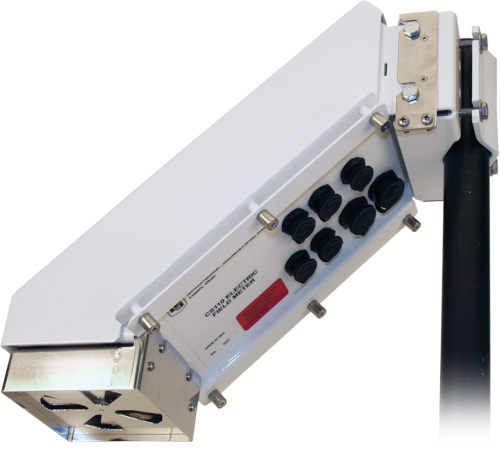
El CS110 se usa en aplicaciones para aviso de rayos, y en investigación para la medida del campo eléctrico local. Mide la componente vertical del campo eléctrico atmosférico en la superficie de la tierra. El sensor CS110 normalmente forma parte de un sistema más grande de medida del campo eléctrico. Incluye un datalogger CR1000, y por tanto, se pueden conectar otros sensores y periféricos.
Vea como el CS110 ayuda a determinar el peligro de rayos en eventos atléticos de escuelas de Utah (después del anuncio de 15 segundosl).
Video Courtesy of KSL.com
Leer másVentajas y características
- Bajo consumo
- Detecta potencialidad de tormentas eléctricas, pudiendo avisar antes de que se produzcan rayos
- Fácil mantenimiento—el estator se puede desmontar fácilmente para su limpieza
- El auto-chequeo de diagnósticos de cada medida reduce o elimina el mantenimiento programado
- Construcción robusta
- El equipo SG000 Strike Guard puede usarse conjuntamente con nuestro CS110 para crear un completo sistema de medida de impactos de rayos y análisis
Imágenes

Descripción detallada
The CS110 uses a reciprocating shutter instead of the traditional rotating vane field mill. The reciprocating shutter is electrically connected to ground potential by a flexible stainless-steel strap. The strap operates below its fatigue limit, resulting in an ultra-reliable electrical ground connection to the shutter.
The reciprocating approach provides better low-frequency error performance than the traditional rotating vane field mill because it has a convenient zero-field (closed shutter) reference. The zero-field reference allows the CS110 to measure and then correct for electronic offset voltages, contact potentials, and leakage currents of each individual measurement (Patent Pending).
The CS110 also contains circuitry to measure and compensate for insulator leakage currents occurring on the charge amplifier input, eliminating measurement errors caused by fouled insulators. If insulator surfaces become conductive because of surface contamination, a leakage current compensation circuit applies an equal and opposite polarity current to the charge-amplifier input that prevents saturation of the electronics.
Warranty
The CS110 has a one year warranty against defects in materials and workmanship. Campbell Scientific does not warrant that the CS110 will meet customer’s requirements or that its operation will be uninterrupted or error-free.
Atmospheric or local electric field conditions or different site characteristics may cause false information, late data, or otherwise incomplete or inaccurate data. The CS110 only measures conditions that make lightning more likely. Just as with weather forecasts, the CS110 measurements only help assess the probability of lightning. Lightning can occur causing personal injury, even death, or damage to property without any warning from the CS110.
Campbell Scientific is not liable for special, indirect, incidental, or consequential damages from the use, failure, or malfunction of the CS110. A full statement of the CS110’s Warranty is contained in the CS110 Manual.
Preguntas frecuentes
Número de FAQs relacionadas con CS110: 6
Expandir todoDesplegar todo
-
To simulate a lightning strike to the SG000, use a camera flash to flash the glass bulb from a distance of 5.08 to 7.62 cm (2 to 3 in.). Note: A flash from a cell phone usually isn't large enough to simulate a lightning strike.
To simulate high electric fields on the CS110, run a comb through your hair and hold it a distance of 2.54 to 5.98 cm (1 to 2 in.) from the shutter of the CS110. Other items such as plastic bags or balloons, or fur on glass, can be used as well.
-
The following information can help determine the effective range (spatial range) of the CS110:
- Thousands of miles: When there are no clouds in the sky, the CS110 responds to what is called the fair weather electric field created by the “global electric circuit.” Thunderstorms worldwide transfer charge to the upper atmosphere, which comes down worldwide as an electric field that varies from roughly -100 to -200 v/m on flatland sites. Our customers have indicated that the fair weather electric field is enhanced by high terrain. Interestingly, there are daily and seasonal changes to this global electric circuit.
- 20 miles: Lightning strikes in thunderstorms as far as 20 miles away are discernable in the fair weather electric field from a flatland site. The strikes show up as sharp changes in the electric field followed by a more gradual recovery. It is unknown if the distance is greater on a high ridgeline.
- 5 to 7 miles: When charged clouds are within five to seven miles, they can positively or negatively change the electric field above or below the fair weather electric field. Even when the actively producing cloud-to-ground lightning portion of the storm is 20 miles away, an anvil cloud from that storm that comes within five to seven miles of the CS110 will change the electric field measured by the CS110. Think of clouds attached to an active thunderstorm as electrical conductors. Even anvil clouds that were once part of a thunderstorm that has since dissipated will hold their charge for a significant period.
- A mountain between a charged cloud and the CS110 will block the electric field influence that the cloud would have had on the CS110.
For more information on this topic, refer to the “Cumulonimbus” section (section 3.2) of the book Lightning: Physics and Effects by Vladimir A. Rakov and Martin A. Uman.
-
The CS110 and the tower should be positioned away from each other a distance of three times the tower’s height.
If the radio signal is strong enough, the SG000 may pick it up as one of the two components the SG000 measures to detect lightning. If this signal coincides with a light flash from a windshield or headlight, it could generate a false strike signal. Also, constant bombardment of the SG000 by sufficiently strong RF signals will pull the sensor out of its quiescent state, affecting its current drain. This will eventually degrade the battery and shorten its expected four-year lifespan.
-
When programmed as a “Slow Antenna” sampling at 100 Hz, the CS110 would provide polarity information but not actual current flow in the wire; therefore, Campbell Scientific does not recommend using a CS110 for this purpose.
-
The CS110 uses the same gas discharge tubes, etc., so it provides similar surge protection as the CR1000. The ground paths are different, although both are intended to provide a good ground path through the ground lug on the wiring panel and the case ground hardware on the CS110.
-
The FC100 is required to communicate with the SG000 Strike Guard Lightning Sensor. The SG000 is an option for the CS110 Electric Field Sensor and the LW110 Lightning Warning System.
Compatibilidad
| IMPORTANT! An embedded CR1000M datalogger module (ordered as p/n 18292) is required for every CS110 purchased; see Common Accessories in ordering information. Generally, the CS110 should be run with the latest released CR1000 operating system (OS) available via "Support" on this website. However, CR1000 OS version 27.05 should NOT be downloaded to standard CS110s. OS version 27.05 was built to accommodate the ~40,000 v/m efields measured on ocean buoys. The special OS also requires a capacitor change on the CS110 panel board. The CS110 should not be run with OS 28 (CR1000.Std.28.obj). A bug in OS 28 prevents changing the setup "Constants" via the keyboard or the terminal emulator. |
Data Logger Considerations
The internal CR1000M (required) can be interfaced to another data logger via the Power/SDM cable if the application requires an additional data logger.
Programming
The CR1000’s on-board programming language, CRBasic, provides data processing and analysis routines that support user control over sample (measurement) rates and setting of alarm conditions. LoggerNet Datalogger Support Software facilitates programming, communications, and data retrieval between the CS110 and a PC.
Using the CS110 as a Weather Station
The CS110 has sealed connectors for attaching meteorological sensors and three digital control ports for controlling external devices and/or triggering alarms. The embedded CR1000 datalogger measures the sensors, processes the measurements, stores the data in tables, and can initiate communications.
Compatible Sensors
| Connector Label | Compatible Sensors (one sensor per connector) |
| Temp/RH | HMP60-L4-C Vaisala Temperature and RH Probe (RH sensing element is field replaceable.) |
| Wind | 05103-L4-C RM Young Wind Speed/Direction |
| Solar | CS305-ET Apogee Pyranometer, CS100 Setra 278 Barometer (barometer connects to the CS110 via the 17460 cable; barometer is typically housed in the LW110 enclosure), GPS16X-HVS Garmin GPS Sensor |
| Rain | TE525-L25-C Texas Electronics rain gage or TB4-L25-C HS Hyquest Solutions rain gage |
Compatible Communication Devices
Communication options compatible with the embedded CR1000 include direct connect, Ethernet, phone modems (land-line and cellular), radios, short haul modems, GOES satellite transmitters, and multidrop modems.
Zero Electric Field Cover
The 17642 Zero Electric Field Cover (ordered separately) is used to check the electric field offset voltage of the CS110. If the measured electric field is ≥|60 V/m| with the Zero Electric Field Cover on, then inspection and cleaning of the electrode surfaces is recommended.
SG000 Strike Guard Lightning Sensor
The SG000 (ordered separately) can be used in conjunction with our CS110 to create a complete lightning-threat measurement and analysis system. This system combines the advantages of two complementary lightning-warning technologies. The SG000 reports actual lightning strikes occurring at distances up to 20 miles—providing a comfortable warning time for incoming storms. The CS110 reports electric fields associated with local thunderstorm development—providing a warning prior to lightning strikes.
Especificaciones
| -NOTE- | An embedded CR1000M datalogger module (ordered as pn 18292) is required for every CS110 purchased; see Common Accessories section on Ordering Information page. |
| CE Compliance Standards to which Conformity Is Declared | BS EN61326:2002 |
| Lightning Protection | Multi-stage transient protection on all external interfaces |
| Power Requirements | 11 to 16 Vdc |
| Baud Rates | Selectable from 300 to 115.2k bps |
| ASCII Protocol | One start bit, one stop bit, eight data bits, no parity |
| Operating Temperature Range |
|
| Operating Relative Humidity | 0 to 100% RH |
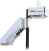
| Mounting | Vertical pipe with outer diameter of 1.91 to 6.35 cm (0.75 to 2.5 in.) |
| Communication Ports |
|
| Dimensions | 15.2 x 15.2 x 43.2 cm (6 x 6 x 17 in.) |
| Weight | 4 kg (9 lb) |
Current Drain |
|
| Peak Current Demand | 750 mA (occurs during motor operation) |
| Average |
|
Accuracy |
|
| -NOTE- | Refer to the sensor manual for resolution, sensitivity, and noise specifications. |
| Parallel-Plate Configuration | ±1% of reading + 60 V m-1 offset |
| 2 m CM110 Tripod Configuration | ±5% of reading + 8 V m-1 offset |
Documentos
Folletos producto
Casos de aplicación
Conformidad
Descargas
CS110 Example programs v.1 (3 kB) 05-05-2020
A CS110 weather station program and a CS110 transfer standard site calibration program. The weather station program measures electric field, rainfall, wind speed and direction, solar radiation, relative humidity, air temperature. The calibration program measures panel temperature, battery, internal relative humidity, and electric field.
Casos de aplicación
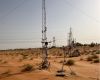
Overview In the heart of the UAE’s Empty Quarter desert—one of the harshest and least hospitable......leer más

CS110 Electric Field Meter to Recreate the Carnegie Curve of Earth's Fair-Weather Electric Potential Gradient INESC......leer más
On March 14, 2016, the European Space Agency (ESA) launched the first mission in the......leer más
The Professional Golfers’ Association Tour (PGA Tour) of America contracted with Schneider Electric to provide......leer más
The Professional Golfers’ Association Tour (PGA Tour) of America contracted with Schneider Electric to provide......leer más
Lightning strikes are a serious concern for school officials who are responsible for protecting the......leer más
Lightning kills about 40 people a year in the highland areas of Peru. This startling......leer más