Este producto ya no está disponible y ha sido reemplazado por: CR1000. Algunos accesorios, recambios o servicios pueden todavía estar disponibles.
| Services Available |
|---|
Resumen
The CR10 was a predecessor of the CR10X. The CR10X was eventually replaced with the CR1000. The CR10 consisted of a CR10M Measurement and Control Module and a CR10WP Wiring Panel.
Leer másVentajas y características
- Manufactured from 1987-1996
- Formato de datos tipo array
- Todavía se repara
Imágenes
Descripción detallada
The CR10 had 12 single-ended (six differential) analog input channels, three switched excitation outputs, eight input/output control ports, two pulse counting channels, and a serial I/O port. It provided sensor measurement, timekeeping, data reduction, data/program storage and control functions. Up to 29,908 data points were stored in it's internal memory.
CR10s manufactured after 1 December 1993 (SN>19273) contained an internal jumper that supported use of 2 or 4 kbytes program memory (appropriate PROM also required).
Especificaciones
- 12 single-ended (six differential) analog input channels
- Three switched excitation outputs
- Eight input/output control ports
- Two pulse counting channels
- One serial I/O port
- Stored up to 29,908 data points in internal memory
Compatibilidad
A typical field-based CR10 system consisted of:
- CR10 with OS10 Operating System
- Alkaline or Rechargeable Power Supply
- Weatherproof Enclosure (CR10s ordered with an environmental enclosure were mounted on the enclosure backplate at the factory)
CR10 peripherals such as the CR10KD and CR10TCR, as well as sensors and data retrieval peripherals, were added to complete the system.
Documentos
Folletos producto
Preguntas frecuentes
Número de FAQs relacionadas con CR10: 2
-
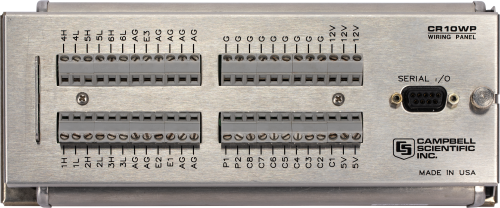
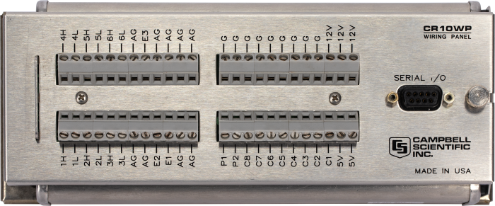
The CR10 and CR10X can use the same wiring panel. The original CR10 wiring panel design was improved by doing the following:
- Increasing the hole size in the screw terminals to accommodate several wires
- Adding ground terminals for sensor shield wires
- Labeling terminals for SDM devices
- Decreasing the profile to fit inside a 4 in. pipe
- Improving control port protection
-
A practical maximum is to connect one multiplexer per every two control terminals on the datalogger. Control terminals can be shared between multiplexers to increase the number of connected multiplexers. Sharing terminals, however, requires more complex wiring and programming. Users who would like to connect more than one multiplexer per every two control terminals are advised to contact a sales or support engineer at Campbell Scientific for assistance.
Casos de aplicación
In an era when water is becoming a precious resource, the Emery Water Conservancy District......leer más
More than 50 CR10-based monitoring systems were used for structural monitoring during the construction of......leer más

Dunhuang (population 100,000) is on the southwestern edge of the Gobi Desert and is situated......leer más
The Problem Our customer required a data acquisition and control system to monitor a slowly moving......leer más
The Poulsbo Marine Science Center is a non-profit educational facility located on Liberty Bay on......leer más
Following an inspection a decade ago, the Welsh Office was advised to reduce the allowable......leer más
The Space Shuttle Endeavor carried the CR10 and CR9000 dataloggers into orbit as part of......leer más
In a country as large as Argentina, monitoring growing conditions in different agricultural regions is......leer más